“It looks amazing!”
That’s what people are saying after seeing TVs that contain QD color filters. No, I have not seen one for myself, but you and I may soon have that opportunity.
Quantum dot (QD) color filters are becoming a hot topic in the display world lately, so I thought it would make sense to educate people on this technology and how it may change the quantum dot display (QLED) landscape. I wrote in the past about quantum dots on-chip as a game-changing technology for displays and lighting (which is true) but many people believe that QDs may find their way into color filters before they make it on-chip.
A quick thank you upfront to folks at Samsung, Nanosys, and Nanoco who were willing to talk with me about their work on QD color filters in preparation for this blog post. My readers and I appreciate it!
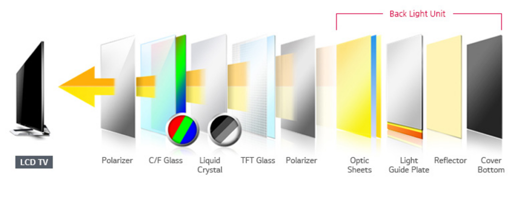
This blog post will require an understanding of how an LED/LCD display (like your tablet, computer monitor, or TV) functions. If you are not familiar, I recommend reviewing this technology in the following video (there are many others out there, this is just one example with good animation, if you want a more in-depth review, look here). The structure below also outlines the various components in a modern display so you can see where all the components are in relation to one another. It could be useful to refer back to this image throughout this post.

What are color filters?

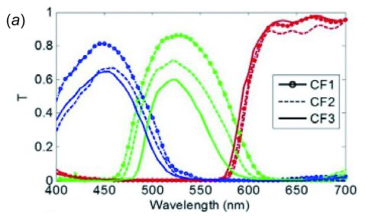
In this post, I’ll be focusing on the color filter portion of a display. Current color filter technology acts as a passive optical component. The one in your TV probably employs a colored material that has been engineered to block the light of certain wavelengths and lets others through. When coupled with the selective transmission of light through any combination of sub-pixels (via LCD), the result is a full-color pallet using R-G-B primaries. The diagram to the right shows various color filters for red, green, and blue transmission. Notice that they overlap significantly in some areas (leakage into other color channels). This overlap contributes to poor color rendering in TVs that do not employ quantum dots.
Implementing quantum dots as color filters

Advantages of QD color filter over QD film
QD color filters have the potential to offer some great benefits beyond what QD films can provide. These benefits include (in no particular order):
• Brighter/more efficient – Light conversion (blue to red/green) happens after the liquid crystal layer and other optical films. This can bring huge improvements in efficiency and brightness (see the table to the right from Nanosys)
• Wider viewing angle – QDs emit in all directions and are closer to the front of the screen. As viewers, we should see a dramatic difference in wide-angle viewing.
• Lower light flux and temperature – Further from the LED source and after the liquid crystal and polarizers means it’s a less harsh environment for the QDs to withstand.
• Thinner panel – Reduced components and in-cell polarizer means an overall thinner display.
These are just a few of the advantages of QD color filters over QD films. I know what you are thinking if there are all these advantages, why haven’t people already done this?
Technical hurdles
No new technology comes easy, and QD color filters are no exception. The technical challenges associated with this technology are very different than the challenges required to implement QD films. Scientists have been working on overcoming these hurdles, many of which have seen significant progress recently.
• Polarizer redesign – Due to the fact that QDs depolarize light, the 2nd polarizer must move before QDs in the optical path (in the cell). According to Samsung, this is a problem that is solved on the R&D scale but still needs to be scaled to manufacturing. Other display makers are likely working to accomplish the same thing.
• Air processing – The deposition and patterning process for color filters will require QDs to be stable in the air. This is no small feat, as the processing requirements for photoresist patterning include multiple UV-curing, developer washes, and high-temperature baking steps.
• Unintentional excitation – neighboring green pixels could unintentionally excite red pixels. QDs can also be excited by blue room light. Additional filtering is needed, perhaps even retaining a color filter on top of the QD color filter layer so that blue room light does not excite the QD layer.
• QDs emit in all directions – This is a light management problem. Partially solved by including a short-pass reflector to maximize light output, but further optimization of light will improve efficiency and brightness.
• Custom QD/polymer mixtures – Patterning will require the use of photoresist polymers or inkjet printable polymers which will be different than the polymers used for films. In addition, these mixtures will need to have a very high concentration of QDs to achieve complete absorption.
• Efficiency/reabsorption – Due to the extremely high concentrations required for this application, reabsorption of emitted photons is a problem. QD concentrations too low will allow blue light to leak through resulting in the reduced color gamut. QD concentrations too high will result in poor device efficiency. The following plots from Nanoco do a great job explaining this difficult trade-off. As the %Abs of blue light increases, the QD efficiency (EQE) drops off dramatically. This is due to the significant overlap between the QD absorption (blue trace) and emission (green trace).